
Cunningham auto
Par Serge
Un petit topo sur les cunningham automatiques avec pour objectif de tendre au prés et de relâcher au portant. Sur la page, des réalisations de frangins et copains, et des trouvailles sur le net..... à ce propos, je ne peux que conseiller d'aller jeter un oeil ici: http://www.onemetre.net/index.htm, c'est riche comme tout, si j'avais le courage de traduire tout ça......
extrait et merci Lester Gilbert
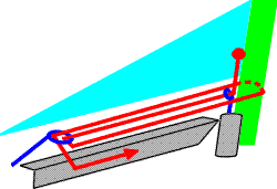
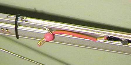
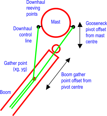
A while back I noticed that some of the top IOM boats on the UK ranking circuit were sporting a baroque down haul or Cunningham arrangement. The idea was that the mainsail luff was pulled tight on the beat, but on the run the tension was automatically eased. In order to do this, the down haul line has to be taken around the mast from the boom, so that the geometry of the gooseneckoffset eases the line in just the same way that it increases the sail draft. The first picture gives an overall impression of the required arrangement, and the schematic diagram illustrates the line run more clearly.
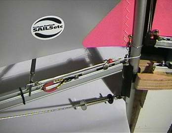
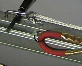
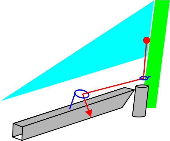
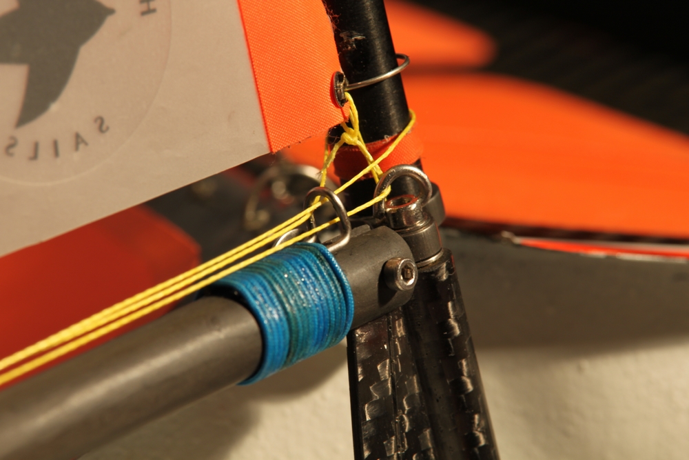
In overview, the line starts from the Cunningham eyelet on the main and runs through an eyebolt on the gooseneck towards the eye of a hook on the top surface of the boom. The hook eye is just a convenient way to turn the line. It runs around the mast and returns to the hook eye, then descends through a slot on the top surface of the boom to its attachment. The way I make it, the line attaches to a length of elastic. The second photo shows this elastic very loose; in practice, it would hold the line tensioned on the beat, and then relax for the run. The arrangement allows the tension of the elastic to be varied, and for different lengths of elastic to be used as required. (Notice the screwdriver blade in the photo is just to lever the hook up away from the boom so the detail is visible. It isn't part of the arrangement!)

Where the line runs along the top of the boom to and from the mast, it is routed through a bead and a wire loop on an adjustable slide. The bead keeps the line runs together, and the wire loop keeps the bead as close to the gooseneck as required. The closer to the gooseneck, the less the easing of the line on the run; alternatively, the further from the gooseneck, the more the easing of the line on the run. We are talking here of just a few millimetres, but it makes a difference. I've now developed a spreadsheet (around 30 kb) to estimate the amount of easing; details below.
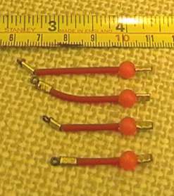
These are a set of graded length elastics for the ball-raced gooseneck, made from 2.2mm diameter silicone "roach pole" elastic from the local fishing store. From beating to running, the Cunningham line eases 8mm on my setup. For the shortest 15mm elastic, 8mm is equivalent to a tension reduction of about 200gm, while for the longest 30mm elastic this equates to 100gm. I use the 30mm elastic for my Rod Carr No.1 suit; Rod recommends a downhaul tension of no more than 4oz, which is 100gm as near as makes no difference.
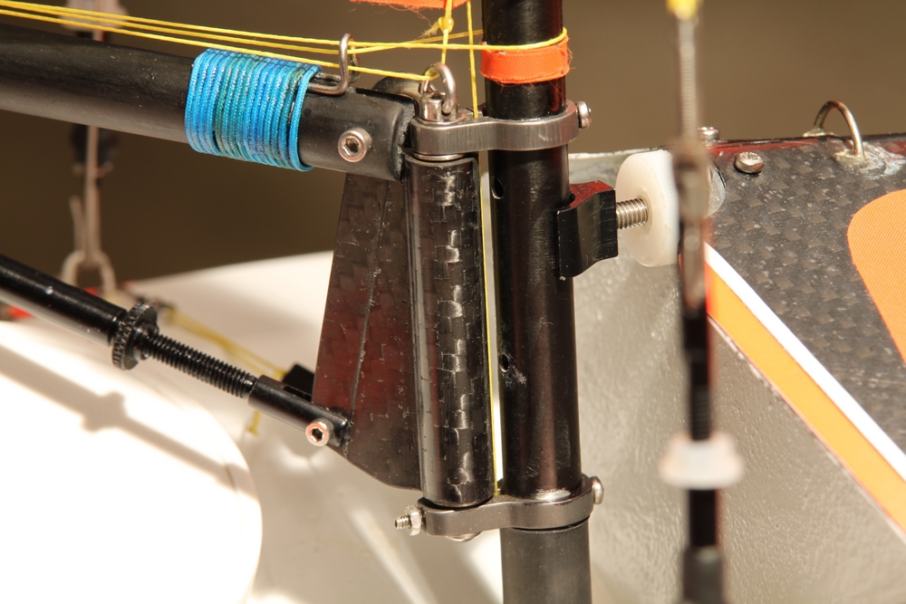
Because the line tension acts so as to pull the boom towards the mast, two effects must be noted. First, since the line runs along the top of the boom, it tends to pull the boom up and against the kicking strap. This may or may not be desirable, depending upon whether you want the weight of the main boom tightening the main leech or not. It may also make the illustrated arrangement illegal according to the IOM rules, but we don't think so. Both the mast and the main boom are permitted to have attachment points for the mainsail tack, while the kicking strap continues to act "in tension only" as required. The only possible grey area is whether the gooseneck body is permitted to have an eyelet through which the tack line runs...
The second thing to note is that a ball raced gooseneck is really needed if the arrangement is to be used in light airs. Because the boom is pulled in to the mast, it can be held there on one side or the other, and not swing over easily. The tension would have to be slackened anyway for light air, but an "ordinary" gooseneck would probably have too much friction. Also, having a ball raced gooseneck would avoid any problem with the rules, since it is the boom end fitting which would provide the path for the tack line, bypassing the gooseneck body completely.
This is the geometry of the automatic downease modelled by the spreadsheet.
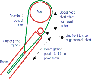
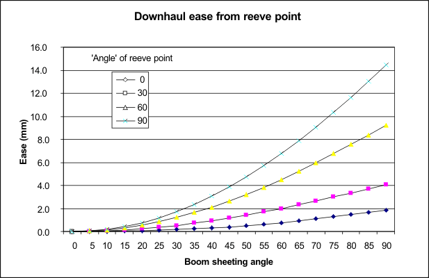
The important inputs are mast diameter, the amount that the gooseneck pivot is offset behind the mast, the distance the "gather" point of the downhaul control line is set behind the gooseneck pivot, and whether one side or other of the downhaul control line touches and is then held to the side of the gooseneck pivot or not. In the photos above, you can probably see that the eyebolt I have at the gooseneck pivot rises above the boom so that the downhaul line does set up against it when the boom sheets out. The result is a graph similar to the following.
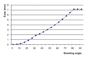
You can see that for my set-up -- 11.1 mm mast, 5 mm gooseneck offset behind the aft face of the mast, and 20 mm between the gather point and the pivot -- total easing of the downhaul is about 7 mm at 80 degrees of sheeting angle. At about 30 degrees sheeting, you can see that the ease is about 2 mm, and that there is a little cusp in the graph at this point. This is the point where the downhaul control line sets against the eyebolt at the gooseneck pivot.
The 'original' autoeasing Cunningham arrangement had quite a lot of line running around the mast and up and down the boom. I've been looking at some simplifications, and have explored some ideas I've seen on Graham Bantock's yachts.
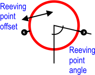
The first idea is to have the Cunningham line running through two reeving points, either side of the mast at the level of the boom.
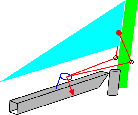
The second, simplest idea, is to have a single the line running through just one reeving point *on the mast*. Note that the spreadsheet does *not* model the situation where the reeving point is on the *boom*. Maybe in version 3...
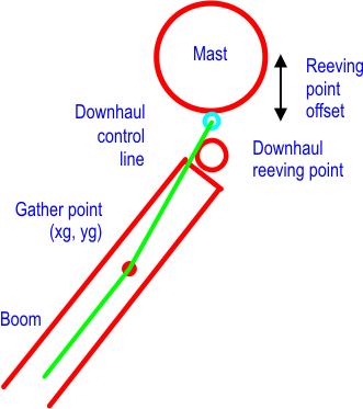
In both cases, the interesting question is what happens when we change, amongst other things, the distance between the reeving points and the gooseneck pivot axis.
I've now developed a second spreadsheet (version 2.1, around 61 kb) to estimate the amount of easing. This version goes a little further than the previous version, since it now also models what happens to the Cunningham (or downhaul) line from the tack of the mainsail to the reeving point on the mast. In this sense, it models the complete run of the line, and not just the part that runs between the boom and the mast.
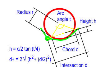
The spreadsheet makes some simplifying assumptions. One is that the tack point is the same offset distance from the mast as the reeving point; this is fine for 'normal' situations. Two is that the wrap around the mast of the line, illustrated by the green thick line in the above diagrams, can be approximated by the hypotenuse of two triangles; that is, I've not modelled the wrap as a helix, although the second page of the spreadsheet gives you the relevant formulae if you'd like to do that. Three is that the reeving points are in the same horizontal plane as the gather point on the boom.
But most importantly, fourthly, the spreadsheet assumes that the tack rotates around the mast in synchrony with the boom. This means that, if the spreadsheet shows the Cunningham line with, say, zero release or ease, that's fine -- it means the tack has just enough line which allows it, in theory, to rotate as needed.
The following graph illustrates the situation with a 11 mm dia mast, a gooseneck whose pivot is 5 mm aft of the mast (hence giving a 10.5 mm pivot offset), reeving points which are just 1 mm proud of the mast (hence 6.5 mm reeve point offset), a tack which is 15 mm above the reeving points, and a gather point 20 mm aft of the gooseneck pivot.
You can see that the downhaul line eases substantially, somewhere between 2 mm and 15 mm when the boom is right over at 90 degrees, depending upon the reeving point angle (how the points are arranged around the mast).
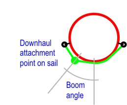
The special case when the reeving point angle is 0, is illustrated by the second graph. This graph shows what happens when the gather point is positioned closer to the gooseneck pivot point.
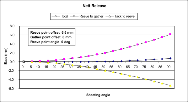
You can see that the line eases very slightly (around 0.8 mm), and this might be an ideal outcome -- this means that the tack has just enough line to rotate with the boom, but not so much that the line is flapping around too loose and allowing the luff to creep up the mast and belly out in a blow...
Sur l'ex de Laurent, donc celui de serge P:

Et Alberto Spada vient de poster cela sur facebook:
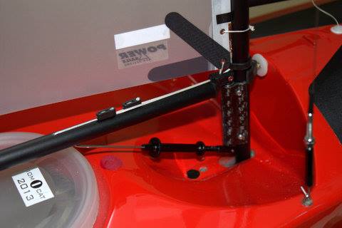
C'est celui du C.O.M. de serge
Libre à chacun de venir compléter ce document 
Date de dernière mise à jour : 05/07/2021
Commentaires
-
 et que je me paluche savoir si je compense avec un élastoc, ou si je modifie pour de bon..... solution N°2 je pense.
 -
et be! je viens de finir un super système, qui marche à merveille! trop bien même.... tellement bien que j'ai 2 cm de course de tension.... donc un sac à patates voiles ouvertes
 Bien fait pour moi! Phil m'avait dit.... j'ai pas écouté.... j'ai bouclé devant le mât, j'aurai pas dû... je recommence!
-
 Et ça marche bien sûr même si ca ne remplace les pouces!;)
Laurent -
Sur le site officiel IOM Rémi Brés il me semble l'explique avec photo.
Moins bien qu'ici c'est clair, mais cela peut compléter.
Bravo!
Laurent -
 ceci dit...super le tuto
-
P't1, je comprends l'idée et l'intérêt mais la réalisation...pffffff faut que je digère un peu le truc...