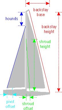
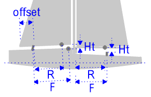
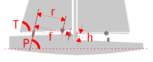
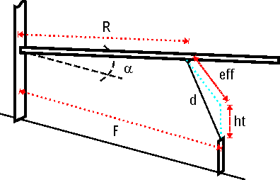
Emplacement du pivot de foc (Macbena)
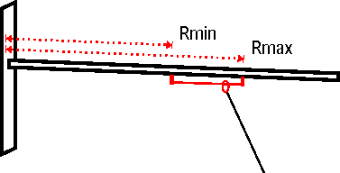
Où placer le pivot entre l'étai de foc et son point d'amure?
Date de dernière mise à jour : 05/07/2021
Commentaires
-
 2100 ça ira mieux dailleurs
-
 OUi il y a beaucoup à piocher sur Lester, et cela demande pas mal de temps pour tout intégrer...
Il faudrait pouvoir intégrer une âme carbone en croix dans nos tubes pour rigidifier les mâts....
Je me demande d'ailleurs s'il n'existe pas du tube carbone avec structure interne... -
 Ah le Lester ... en francais et sans les formules qui font mal à la têteuh, ça doit être bien
-
 Ca se fera JC, un jour ...
Suffit de faire deux demi moules troussés avec armature bien rectiligne et stable, en intégrant une gorge sur la chute ... facile quoi
un petit 8x60x210 vite fait su'l gaz


-
 Bof pour un pro du ponçage comme toi jc c'est de la gnognote lol
 -
 Ben oui j'en rêve d'un mât carbone profilé mais j'ai peur de me lancer dans un moule...çà fait 2m30 de moule et t'imagine le profilage du master sur une telle distance...patateécrasée...ponçage au laser...à moins de faire faire le master au laser....p't1
 -
 Milles excuses les gas, mais suis à fond dans la colle, fait pas bon ménage avec les touches de mon clav
Il y a un tableur excel sur le site de lester vraiment très précis, mais le premier boulot pour l'utiliser et de monter le mât de repérer touts les points de flexions/ tentions et position des haubans. Il est sur que le mât doit être le plus rigide possible, une suggestion pourquoi ne faite vous pas vous même votre mât en forme ?
Cela vos surement le coût pour un tel bateau, et les suivants non..
-
 Merci Serge pour le tuto...super

-
 Oui Laurent, je me doutais un peu de cela et je compte bien tester la forme de mon mât sous tensions (haubans, pataras et étai de foc) dans les différentes positions et calquer la forme du mât pour comparer et en cas de problème je placerai des haubans réglables à l'extérieur de la coque. Ce n'est jamais qu'un proto finalement...Je pense opter pour un mât fort rigide (16mm sur une bonne partie)...Pour le centrage du mât par rapport au centre de dérive, j'ai de la marge dans mes réglages possibles...et puis comme d'hab, j'aurai du bol
-
 Cool,
Cool,
En Français ce serait top!
Laurent -
 Ok JC,
Bien lu tout ce que tu as écris.
Le plus gênant c'est que tu n'es qu'un point de cadène de hauban, mais j'ai bien compris le pb en allant voir les photos.
Pourquoi? Car en fonction de son point de tir plus ou moins en avant ou en arrière du mat il va donner de la flexion à ton mat ( plus ou moins), Sa courbure. Cette courbure doit être maîtrisée et adaptée à ton guindant de GV. Le fait de cintrer le mat absorbe le creux de ta GV.
Si tes cadènes sont trop reculées tu vas trop cintrer juste en mettant ton haubanage sous tension suffisante. Le phénomène va s'accentuer lorque tu prendras du pataras.
Trop avant tu ne vas pas suffisamment cintrer ton mat, il risque d'être mal tenu en longitudinal, voir de s'inverser( cintre à l'envers une catastrophe pou le réglage des voiles, et la vie du mat)
Une chose est certaine c'est que plus ton espar a une rigidité intrinsèque importante (haut module) plus tu minimises les risques, et augmentes la marge de tolérance pour les points d'ancrages.
Pour dégrossir JC calcule le centre de poussée vélique de ton jeu A, et demande à Phil où il estime devoir ce situé par rapport à ton centre anti-dérive.
A partir de là tu as la base.
Après il faut comparer/copier ce qu'il y a sur les autres 10.
Si cela peut aider je peux te transmettre ce que j'ai (plan de voilure, cotes, etc...)
Les ancrages du grément sur la coque ne sont pas complètement définis non plus sur le mien pour le haubanage notamment, on est sur des protos..., et bcp dépend aussi du mat...
Ceci dit la marge est d'erreur est faible, et les réglages de mat, de voiles permettent normalement de compenser le cas échéant qq mms sans problèmes, cms moins sur si l'on veut conserver toute l'énergie potentielle de la machine.
Laurent -
 tu feras bien comme tu voudras JC
 je sens bien pourtant mon plan de voilure....
-
 Pour le plan de voilure je pense qu'on peut franchement descendre en hauteur avec des bordures plus grandes, le premier jeu devrait être aux environs de 0,96m². Je pense que le guindant de la GV devrait se situer entre 2m et 1m95 (le guindant de la GV de NZ2 est à 2m15)
Oui Laurent j'ai bien lu tous les commentaires sur Do it.
Je prévois tout en réglable sauf pour les cadènes de haubans...elles sont situées pour le réglage de ma^t le plus en arrière (pétole en principe) et seront en arrière si j'avance le mât ...le cdènes Bantock ne permettent pas d'en mettre plus qu'une de manière raisonnable.
actuellement:
mât réglable avant arrière
quête de mât
attache pivot de foc sur le pont: avant=arrière
tension du pivot de foc réglable
prévu:
cunningham relâché au largue
attache du pivot de foc sur le foc: avant-arrière
attache pivot de foc sur sa bôme: avant arrière
peut être:
mini servo pour lancer le foc en ciseau
voilà les gars ce qui est prévu sur Do it -
 Nan, je ne livre pas le plan de voilure
 , ni le plan de construction dailleurs
Juste l'emplacement du CV pour affinage
Faut faire comme Serge dit
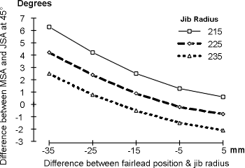
Si tu ne veux pas prendre de risques pour le pivot, ne descend pas sous les 20 %, perso 25% je trouve que c'est un compromis correct, mais je suis moi, tu es toi, et en plus tu est double, alors ...
-
 On part sur un plan de voilure de nz avec corne un peu réduite et corrigée et un foc sensiblement plus grand; on peut partir sur les bases du nz avec +20 sur la bôme de foc dans un premier temps. A ce propos, je dois te passer les cotes exactes, camarade JC, je te fais ça rapidement.
 -
 Dernier point JC,
Tu n'as pas lu la contribution que je t'ai dernièrement sur la construction du DO IT notamment pour un partie de ce sujet?
A plus.
Laurent -
 Et un plan de voilure aussi.
Cela doit te donner les grandes lignes, oui il y aura tjs un delta entre la théorie, et les essais.
A ce titre il me semble que tu as fait un pied de mat réglable il me semble.
De toute façon il te faudra au moins Tois jeu de voile, et grément le mini de mini.
Prévois donc 3 points par coté pour tes haubans, 3 pour le foc, etc....
La cote de ton point de capelage fait partie de ton plan de voilure.
Laurent -
 JC,
JC,
Tu veux toutes les cotes de ton schéma?
Phil a dû te donner un plan d'ensemble pour le grément non?
Laurent -
 ben c'est moi qui pose la question et tu veux que je réponde...?
y a rien sur le net... -
 Faut continuer mon pote et pas nous laisser comme ça!


Vous devez être connecté pour poster un commentaire

